Sequential Logic Circuits
Computer Organization and Digital Design
2nd Semester
Output depends on current inputs and past outputs
- State : Collection of state variables
Sequential logic circuits are also called as finite state machines
Sequential Circuit types
- Feedback sequential circuits: Use individual logic gates and feedback loops for memory
- Clocked synchronous state machines : Use latches and flipflops as building blocks controlled by clock
Latches and Flip Flops
| Latch | Flip Flop |
|---|---|
| Triggered by input level | Triggered by clock edges |
| Asynchronous | Synchronous |
| Can change state while enabled | State change only at clock edge |
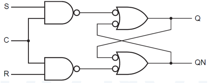
S-R Latch
| Block Diagram | Logic diagram |
|---|---|
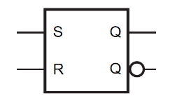 | 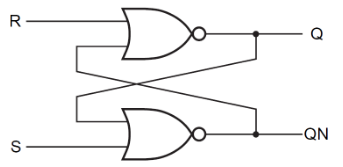 |
| S | R | Q | QN |
|---|---|---|---|
| 0 | 0 | last Q | last QN |
| 0 | 1 | 0 | 1 |
| 1 | 0 | 1 | 0 |
| 1 | 1 | 0 | 0 |
S-R Latch with Enable
| Block Diagram | Logic Diagram |
|---|---|
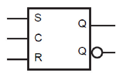 |  |
| S | R | C | Q | QN |
|---|---|---|---|---|
| 0 | 0 | 1 | last Q | last QN |
| 0 | 1 | 1 | 0 | 1 |
| 1 | 0 | 1 | 1 | 0 |
| 1 | 1 | 1 | 1 | 1 |
| x | x | 0 | last Q | last QN |
D Latch
- Stores one bit of information
- A transparent Latch
| Block Diagram | Logic Diagram |
|---|---|
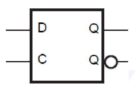 | 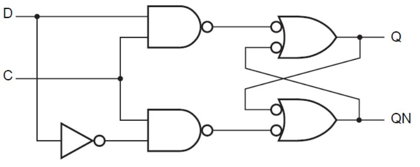 |
| C | D | Q | QN |
|---|---|---|---|
| 1 | 0 | 0 | 1 |
| 1 | 1 | 1 | 0 |
| 0 | x | last Q | last QN |
D Flip Flop
- Output changes only at an edge of a clock signal
- Two Types:
- Positive Edge Triggered
- Negative Edge Triggered
| Block Diagram | Logic Diagram |
|---|---|
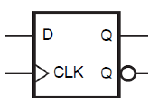 | 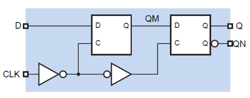 |
| D | CLK | Q | QN |
|---|---|---|---|
| 0 | 0 | 1 | |
| 1 | 1 | 0 | |
| x | 0 | last Q | last QN |
| x | 1 | last Q | last QN |
J-K Flip Flop
| Block Diagram | Logic Diagram |
|---|---|
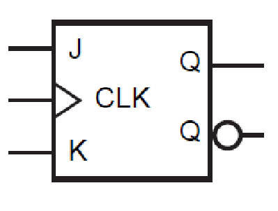 | 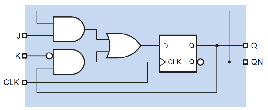 |
| J | K | CLK | Q | QN |
|---|---|---|---|---|
| x | x | 0 | last Q | last QN |
| x | x | 1 | last Q | last QN |
| 0 | 0 | last Q | last QN | |
| 0 | 1 | 0 | 1 | |
| 1 | 0 | 1 | 0 | |
| 1 | 1 | last QN | last Q |
T Flip Flop
- Toggle at every Clock signal
| Using D | Using J-K | D with Enable | J-K With Enable |
|---|---|---|---|
![[Pasted image 20250614163111.png]](/_astro/Pasted%20image%2020250614163111.Dfwk9wDf_kmWeC.png) | ![[Pasted image 20250614163120.png]](/_astro/Pasted%20image%2020250614163120.Bm1qFH8U_xL1k2.png) | ![[Pasted image 20250614163130.png]](/_astro/Pasted%20image%2020250614163130.BWSYgySQ_ZaUeg2.png) | ![[Pasted image 20250614163137.png]](/_astro/Pasted%20image%2020250614163137.kZLZno1t_2l8Pzw.png) |
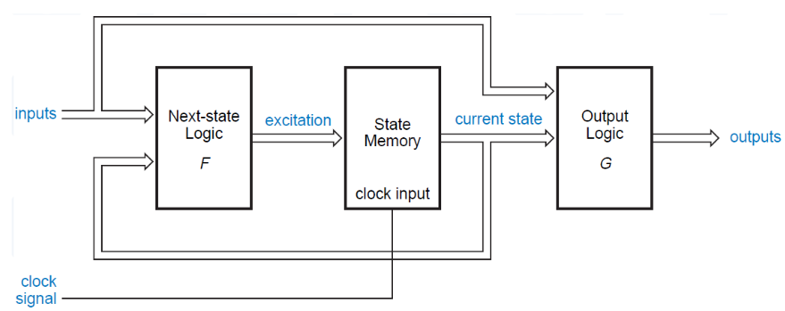
Clocked Synchronous State Machines
- State Machine : Sequential Operation
- Clocked : State change with clock edge
- Synchronous : All flip flops use the same clock
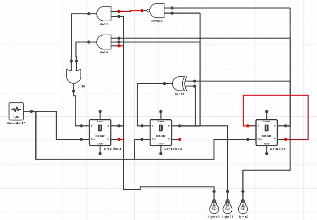
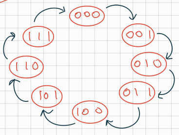
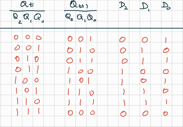
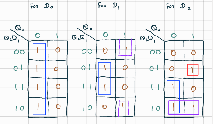
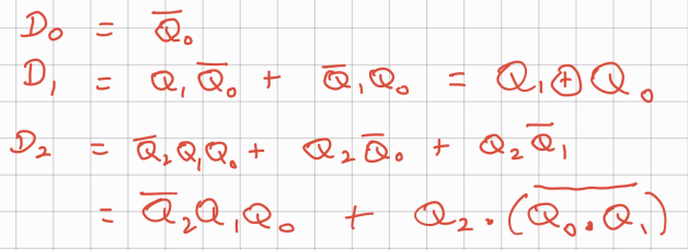
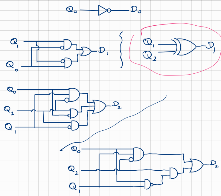
Example: 3 Bit Counter using D-FlipFlops
State Diagram
Excitation Table
K-Maps
Excitation Equations
Logic circuit for Individual Excitations
Complete Logic Circuit
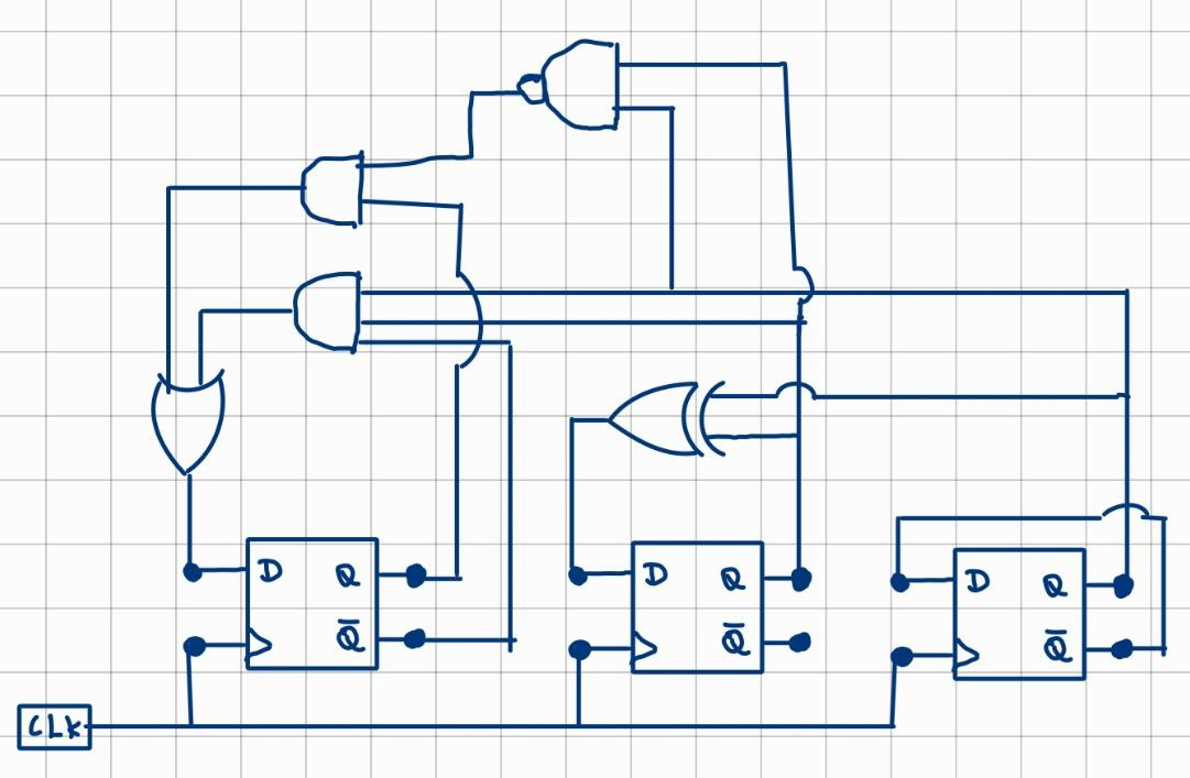
Circuit in Action