Fourier Series
Introduction
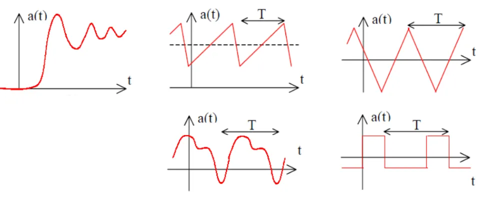
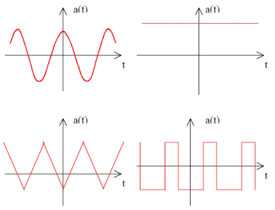
Section titled “Introduction”In electrical circuit analysis, we often encounter waveforms that are not purely sinusoidal. While we’ve mastered DC (constant) and AC (sinusoidal) analysis, real-world signals frequently have more complex shapes that repeat periodically.
What is Fourier Series?
Section titled “What is Fourier Series?”Fourier Series is a mathematical technique that allows us to express any periodic waveform as a sum of sinusoidal components. This powerful concept was developed by French mathematician Jean-Baptiste Joseph Fourier (1768-1830).
Key Concept
Section titled “Key Concept”Any periodic waveform with period
Where:
= DC component (average value) = Fundamental frequency = 2nd, 3rd, 4th harmonics = Fourier coefficients to be determined
Why is this useful?
Section titled “Why is this useful?”Since electrical circuits are linear, we can:
- Apply each harmonic component separately
- Solve for each component individually
- Use superposition to combine all responses
- Get the total response to the original waveform
Waveform Symmetries
Section titled “Waveform Symmetries”Many practical waveforms exhibit symmetry, which greatly simplifies Fourier analysis calculations.
1. Even Symmetry
Section titled “1. Even Symmetry”Mathematical condition:
Properties:
- Left side of y-axis is mirror image of right side
- Contains only cosine terms:
for all - Simplified calculation:
2. Odd Symmetry
Section titled “2. Odd Symmetry”Mathematical condition:

Properties:
- Left side is negative mirror image of right side
- Contains only sine terms:
for all (including DC component) - Simplified calculation:
3. Half-Wave Symmetry
Section titled “3. Half-Wave Symmetry”Mathematical condition:
Properties:
- One half of waveform equals negative of other half
- No DC component possible
- Contains only odd harmonics:
for even - For odd
:
Summary of Symmetry Rules
Section titled “Summary of Symmetry Rules”| Symmetry Type | DC Component ( | Cosine Terms ( | Sine Terms ( |
|---|---|---|---|
| Even | Present | Present | Zero |
| Odd | Zero | Zero | Present |
| Half-wave | Zero | Odd harmonics only | Odd harmonics only |
| Even + Half-wave | Zero | Odd harmonics only | Zero |
| Odd + Half-wave | Zero | Zero | Odd harmonics only |
Calculating Fourier Coefficients
Section titled “Calculating Fourier Coefficients”General Formulas
Section titled “General Formulas”DC Component:
Cosine Coefficients:
Sine Coefficients:
Useful Trigonometric Properties
Section titled “Useful Trigonometric Properties”These orthogonality relationships are crucial for coefficient calculation:
Example 1: Triangular Wave
Section titled “Example 1: Triangular Wave”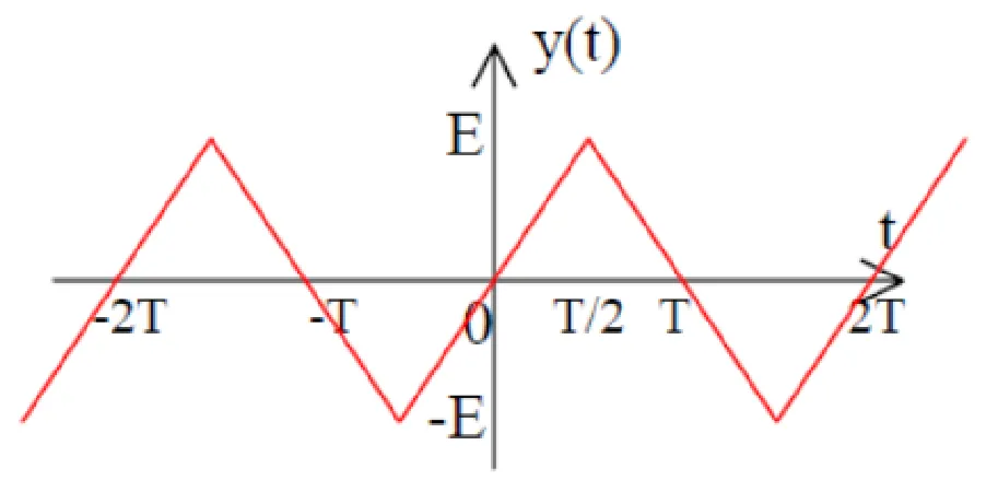
Given: Triangular wave with period
Analysis:
- Mean value = 0 (equal positive and negative areas) →
- Odd symmetry →
for all - Half-wave symmetry →
for even
Calculation for odd harmonics: Using integration by parts:
Let
After detailed integration:
Final Result:
Example 2: Full-Wave Rectified Sine
Section titled “Example 2: Full-Wave Rectified Sine”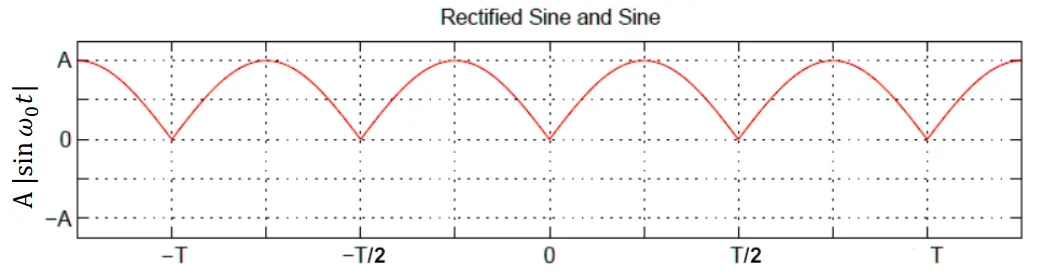
Given:
Analysis:
- Period of rectified wave =
(double frequency) - New fundamental frequency:
- Even symmetry →
for all
DC Component:
AC Components: After detailed trigonometric integration:
Final Result:
Frequency Spectrum
Section titled “Frequency Spectrum”The frequency spectrum is a plot showing the amplitude of each harmonic component versus frequency (or harmonic number).
Harmonic Magnitude:
Phase Angle:
RMS Value of Fourier Series
Section titled “RMS Value of Fourier Series”For a waveform expressed as a Fourier series:
The RMS value is:
Key Point: The RMS value equals the square root of the sum of squares of individual RMS components.
Total Harmonic Distortion (THD)
Section titled “Total Harmonic Distortion (THD)”THD measures how much a waveform deviates from a pure sinusoid:
Where:
= RMS value of fundamental component = RMS values of 2nd, 3rd, 4th harmonics - DC component is ignored in THD calculation
Lower THD = waveform closer to pure sinusoid Higher THD = more distorted waveform