Three Phase Symmetrical Components
What Are Symmetrical Components?
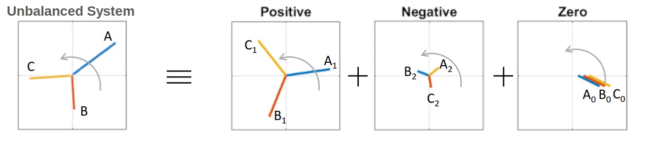
Section titled “What Are Symmetrical Components?”Imagine you have a three-phase electrical system that’s “unbalanced” - meaning the three phases don’t have equal magnitudes or aren’t perfectly spaced 120° apart. This makes analysis very complicated!
Symmetrical components is a clever mathematical trick that breaks down any unbalanced 3-phase system into three simpler, balanced systems that are much easier to work with.
The Three Components
Section titled “The Three Components”Any unbalanced system can be split into exactly three balanced components:
- Positive Sequence (
) - Rotates in the same direction as the original system - Negative Sequence (
) - Rotates in the opposite direction - Zero Sequence (
) - All three phases are identical (same magnitude and phase)
Understanding the Magic Operator
Section titled “Understanding the Magic Operator ”Before we dive deeper, we need to understand a special mathematical tool called the
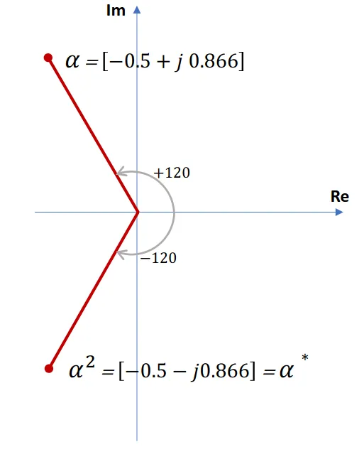
Think of
- rotates a phasor by 120° counterclockwise - rotates a phasor by 240° counterclockwise - back to the original position
In rectangular form:
Key property:
The Transformation Equations
Section titled “The Transformation Equations”Here’s where the magic happens. For any unbalanced system with phases A, B, and C:
Forward Transformation (Unbalanced → Symmetrical Components)
Section titled “Forward Transformation (Unbalanced → Symmetrical Components)”In simple terms:
- Zero sequence is just the average - Positive sequence - Negative sequence
Inverse Transformation (Symmetrical Components → Unbalanced)
Section titled “Inverse Transformation (Symmetrical Components → Unbalanced)”In simple terms:
Worked Example 1: Finding Symmetrical Components
Section titled “Worked Example 1: Finding Symmetrical Components”Problem: A 3-phase generator has unbalanced voltages:
V V V
Find the symmetrical components.
Solution: Using the forward transformation:
Step-by-step calculation:
- Zero sequence:
- Positive sequence:
- Negative sequence:
Final Answer:
V V V
Worked Example 2: A More Balanced System
Section titled “Worked Example 2: A More Balanced System”Problem: Another 3-phase generator has:
V V V
Solution: Notice that this system is “almost” balanced - the phase angles are exactly 120° apart, but the magnitudes are different.
Using the same transformation:
Answer:
V (small zero sequence) V (large positive sequence - this is the “main” component) V (small negative sequence)
Key Insight: Since this system is nearly balanced, most of the energy is in the positive sequence component!
Worked Example 3: Reverse Calculation
Section titled “Worked Example 3: Reverse Calculation”Problem: You’re given symmetrical components of currents:
A (no zero sequence) A A
Find the actual phase currents.
Solution: Using the inverse transformation:
Step-by-step:
Final Answer:
A A A
Power Calculation with Symmetrical Components
Section titled “Power Calculation with Symmetrical Components”Here’s a beautiful property: the total power can be calculated using just the symmetrical components!
For total complex power:
Or in matrix form:
Why is this useful? You can calculate the total power without converting back to phase quantities!
Impedances and Symmetrical Components
Section titled “Impedances and Symmetrical Components”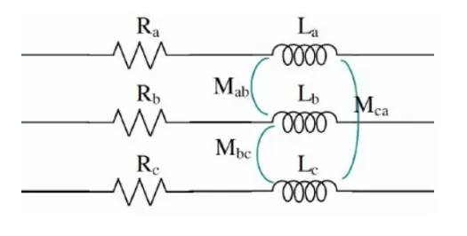
Here’s where things get really interesting for power system analysis:
For Simple Loads (No Mutual Coupling)
Section titled “For Simple Loads (No Mutual Coupling)”Each symmetrical component sees the same impedance. This means:
- Apply each voltage component separately to the load
- Calculate the corresponding current components
- Convert back to phase currents using the inverse transformation
For Complex Systems (Transmission Lines, Machines)
Section titled “For Complex Systems (Transmission Lines, Machines)”The impedances are different for each sequence:
- Positive sequence impedance (
) - for normal operation - Negative sequence impedance (
) - for reverse rotation effects - Zero sequence impedance (
) - for ground current paths
Key Point: This is why symmetrical components are so powerful for analyzing faults in power systems - each type of fault creates different combinations of sequence components!