Transformers
What is an Ideal Transformer?
Section titled “What is an Ideal Transformer?”An ideal transformer is a theoretical transformer with perfect characteristics:
- No copper losses in the windings (zero resistance)
- No leakage flux (all flux links both windings)
- Zero reluctance in the core (infinite permeability)
- No core losses (no eddy current or hysteresis losses)
Basic Transformer Equations
Section titled “Basic Transformer Equations”Voltage Relationships
Section titled “Voltage Relationships”For an ideal transformer, the voltage relationship is:
Where:
= Primary voltage = Secondary voltage = Number of turns in primary = Number of turns in secondary = Turns ratio
Instantaneous Voltages
Section titled “Instantaneous Voltages”For sinusoidal excitation:
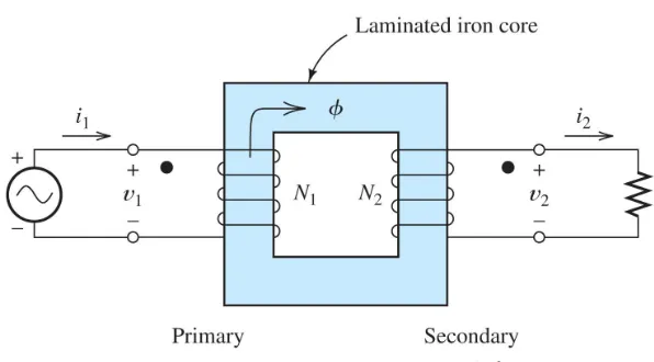
Transformer as Coupled Circuits
Section titled “Transformer as Coupled Circuits”MMF (Magnetomotive Force) Balance
Section titled “MMF (Magnetomotive Force) Balance”The currents
For an ideal transformer with zero reluctance (
Therefore:
Current Relationship
Section titled “Current Relationship”The current ratio is inverse to the voltage ratio.
Power in an Ideal Transformer
Section titled “Power in an Ideal Transformer”Power Conservation
Section titled “Power Conservation”In an ideal transformer, no power is lost:
Since
This confirms our voltage and current relationships.
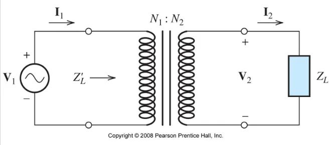
Impedance Transformation
Section titled “Impedance Transformation”Referred Impedance
Section titled “Referred Impedance”An impedance
Where:
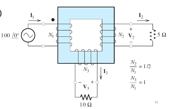
Multi-Winding Transformers
Section titled “Multi-Winding Transformers”Three-Winding Example
Section titled “Three-Winding Example”For a transformer with three windings:
Voltage relationships:
MMF balance:
Current relationship:
Polarity and Dot Convention
Section titled “Polarity and Dot Convention”Dot Notation Rules
Section titled “Dot Notation Rules”- Voltage polarities: When the dotted terminals are both positive (or both negative), the voltages are in phase
- Current directions: Currents entering dotted terminals produce MMFs in the same direction
- Opposing MMFs: For transformer action, currents should enter opposite dot polarities
Practical Example Problem
Section titled “Practical Example Problem”Given: Transformer with
Solution:
- Secondary voltage:
- Secondary current:
- Primary current:
- Power delivered:
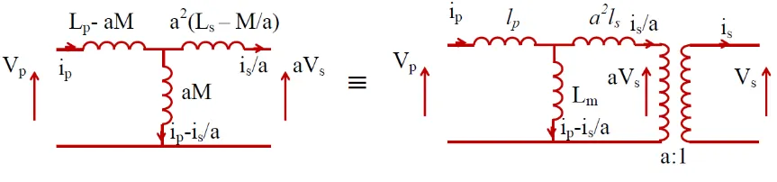
Real vs Ideal Transformers
Section titled “Real vs Ideal Transformers”Transition to Real Transformers
Section titled “Transition to Real Transformers”Real transformers are modeled as mutually coupled coils with:
Where:
= Self inductances = Mutual inductance = Coupling coefficient
Equivalent Circuit Elements
Section titled “Equivalent Circuit Elements”- Leakage inductances:
, - Magnetizing inductance:
Key Takeaways
Section titled “Key Takeaways”- Perfect transformation: Ideal transformers provide perfect voltage and current transformation
- Power conservation: No losses in ideal transformers
- Impedance scaling: Impedances transform by the square of turns ratio
- MMF balance: Sum of ampere-turns equals zero
- Polarity matters: Dot convention determines phase relationships