Fourier Series
Introduction
In electrical circuit analysis, we often encounter waveforms that are not purely sinusoidal. While we’ve mastered DC (constant) and AC (sinusoidal) analysis, real-world signals frequently have more complex shapes that repeat periodically.
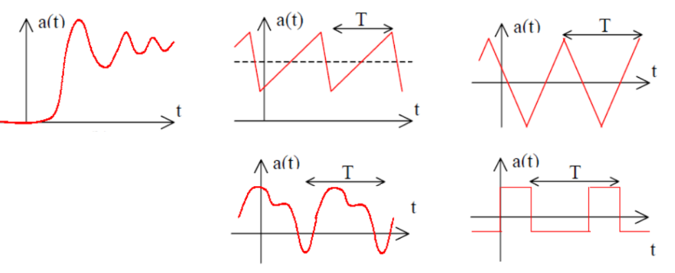
What is Fourier Series?
Fourier Series is a mathematical technique that allows us to express any periodic waveform as a sum of sinusoidal components. This powerful concept was developed by French mathematician Jean-Baptiste Joseph Fourier (1768-1830).
Key Concept
Any periodic waveform with period
Where:
= DC component (average value) = Fundamental frequency = 2nd, 3rd, 4th harmonics = Fourier coefficients to be determined
Why is this useful?
Since electrical circuits are linear, we can:
- Apply each harmonic component separately
- Solve for each component individually
- Use superposition to combine all responses
- Get the total response to the original waveform
Waveform Symmetries
Many practical waveforms exhibit symmetry, which greatly simplifies Fourier analysis calculations.
1. Even Symmetry
Mathematical condition:
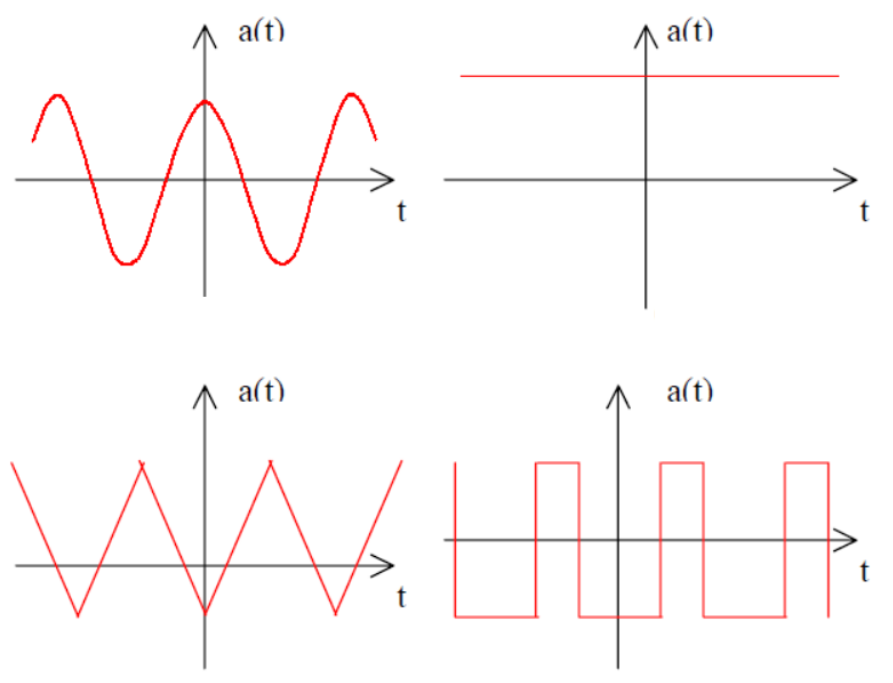
Properties:
- Left side of y-axis is mirror image of right side
- Contains only cosine terms:
for all - Simplified calculation:
2. Odd Symmetry
Mathematical condition:
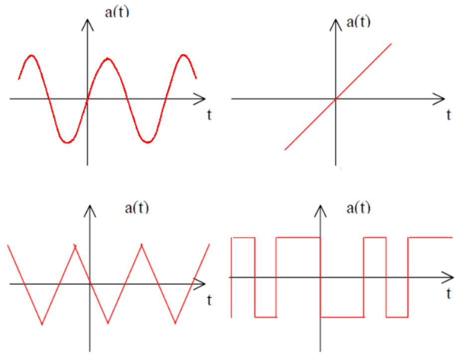
Properties:
- Left side is negative mirror image of right side
- Contains only sine terms:
for all (including DC component) - Simplified calculation:
3. Half-Wave Symmetry
Mathematical condition:
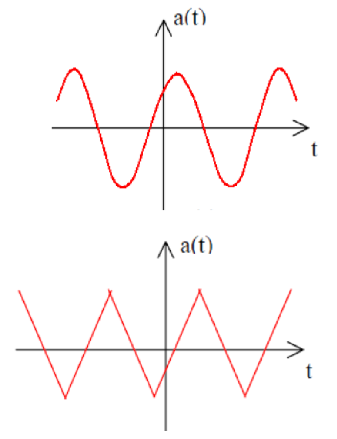
Properties:
- One half of waveform equals negative of other half
- No DC component possible
- Contains only odd harmonics:
for even - For odd
:
Summary of Symmetry Rules
| Symmetry Type | DC Component ( | Cosine Terms ( | Sine Terms ( |
|---|---|---|---|
| Even | Present | Present | Zero |
| Odd | Zero | Zero | Present |
| Half-wave | Zero | Odd harmonics only | Odd harmonics only |
| Even + Half-wave | Zero | Odd harmonics only | Zero |
| Odd + Half-wave | Zero | Zero | Odd harmonics only |
Calculating Fourier Coefficients
General Formulas
DC Component:
Cosine Coefficients:
Sine Coefficients:
Useful Trigonometric Properties
These orthogonality relationships are crucial for coefficient calculation:
Example 1: Triangular Wave
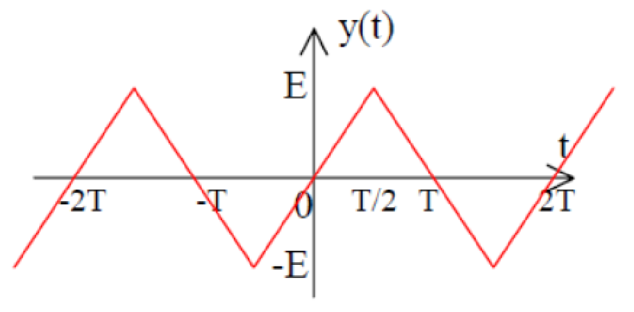
Given: Triangular wave with period
Analysis:
- Mean value = 0 (equal positive and negative areas) →
- Odd symmetry →
for all - Half-wave symmetry →
for even
Calculation for odd harmonics: Using integration by parts:
Let
After detailed integration:
Final Result:
Example 2: Full-Wave Rectified Sine
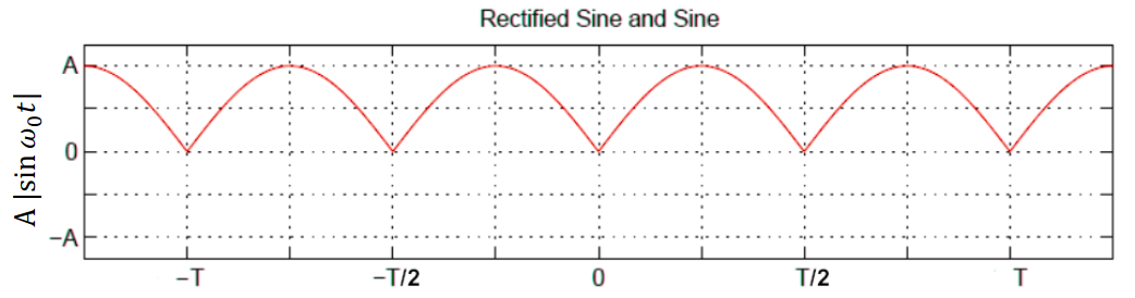
Given:
Analysis:
- Period of rectified wave =
(double frequency) - New fundamental frequency:
- Even symmetry →
for all
DC Component:
AC Components: After detailed trigonometric integration:
Final Result:
Frequency Spectrum
The frequency spectrum is a plot showing the amplitude of each harmonic component versus frequency (or harmonic number).
Harmonic Magnitude:
Phase Angle:
RMS Value of Fourier Series
For a waveform expressed as a Fourier series:
The RMS value is:
Key Point: The RMS value equals the square root of the sum of squares of individual RMS components.
Total Harmonic Distortion (THD)
THD measures how much a waveform deviates from a pure sinusoid:
Where:
= RMS value of fundamental component = RMS values of 2nd, 3rd, 4th harmonics - DC component is ignored in THD calculation
Lower THD = waveform closer to pure sinusoid Higher THD = more distorted waveform